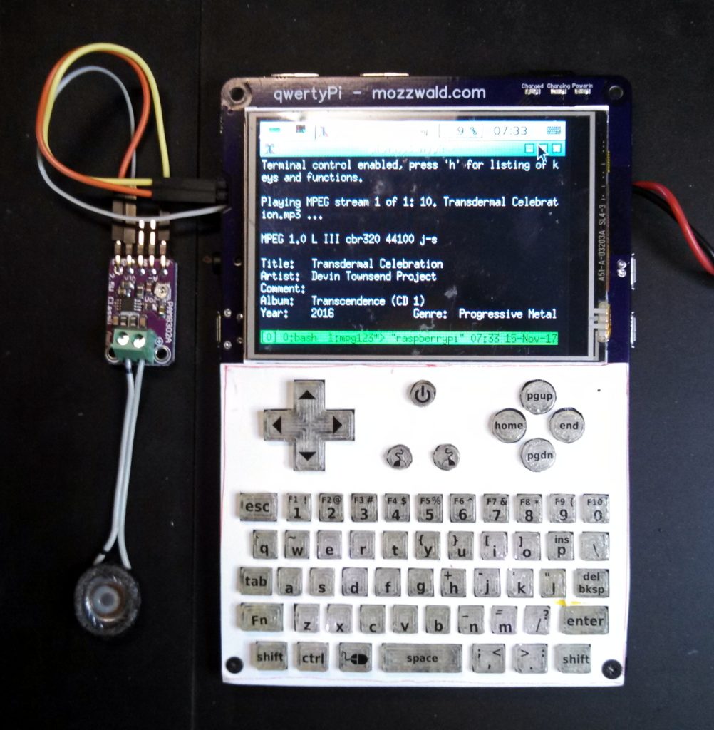
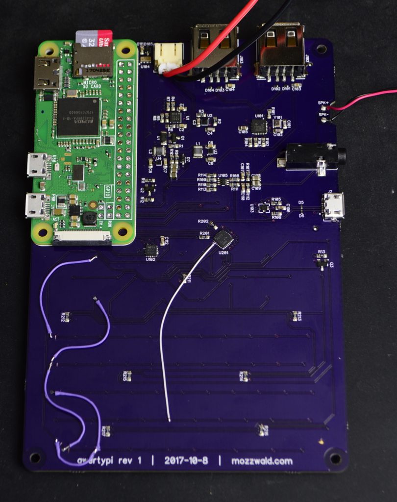
When the first Raspberry Pi 1 Model B was released in 2012, I was fully immersed in the Zipit Z2 community and I had the idea to create my own handheld qwerty Linux computer with the Pi. Back then I didn’t really have the knowledge or skills to follow through with such a project and so it was pushed into the “some day” list. In late 2015, the Raspberry Pi Foundation released the tiny Pi Zero and subsequent Pi Zero W which sparked my interest in building a handheld again. Over that past few months I’ve been working on the first revision of my “qwertypi” handheld computer based on a Raspberry Pi Zero W. The project (more of an experiment) is well under way and I’m already working on a revision 2 pcb to fix my mistakes and change some things around.
This revision 1 prototype has quite a few mistakes that I made in the schematic and layout, but most have been fixed in one way or another. Some of the components used are very fine pitch BGA so this is not a project for the faint of heart. I used some BGA chips because I wanted to test my limits. Luckily, I’ve had no problems with them so far.
Power
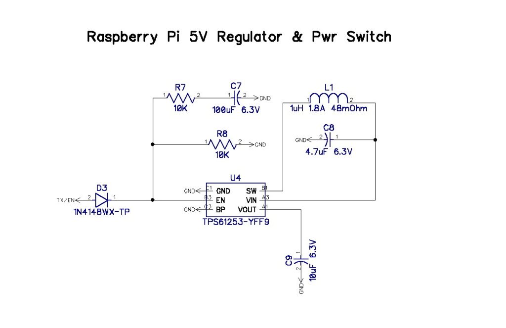
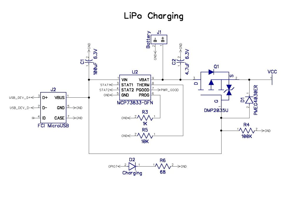
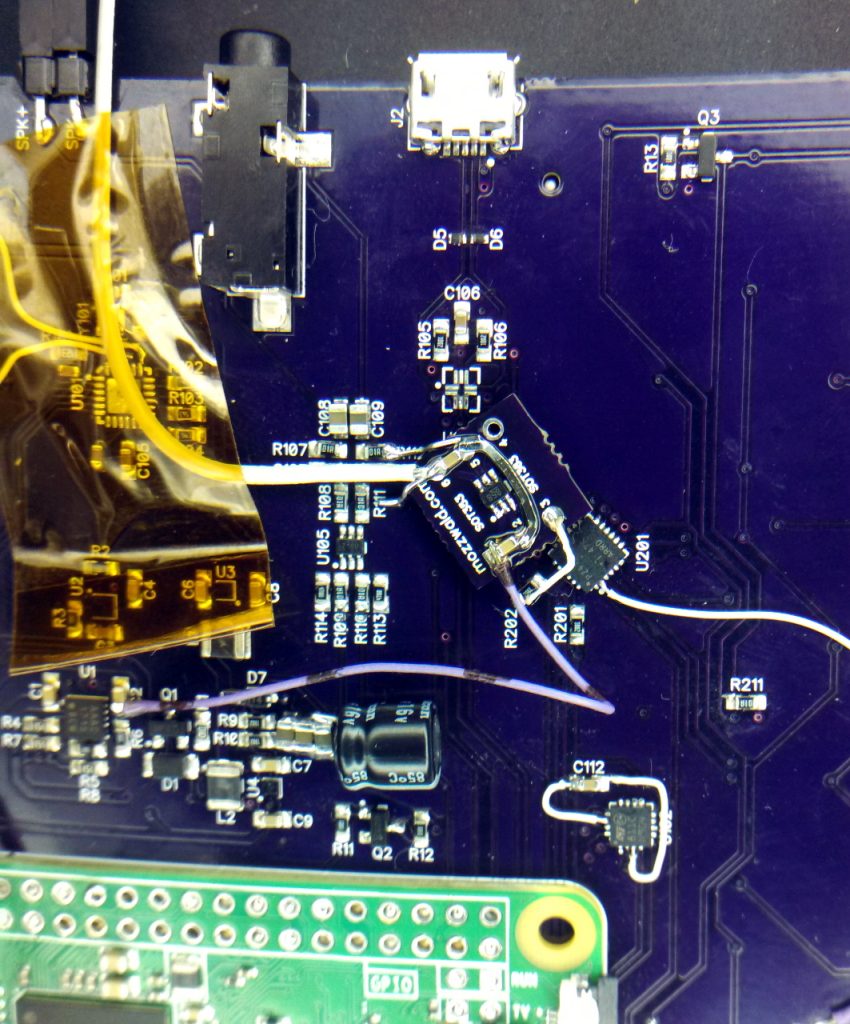
The power circuit is somewhat simple consisting of LiPo battery charging (MCP73833) and 5V boost (TPS61253) circuit. I got the idea of using a MOSFET for load sharing (if plugged in, power input charges battery and powers the system) from Zak’s Electronics Blog. A lot of custom raspi battery power circuits use a microcontroller for the power button on/off stuff. I wanted to keep it simple so I use a diode, capacitor, resistor, switch (snap dome) and the raspi’s serial TX line to enable and shut off the 5V boost regulator. Pressing the power button applies battery voltage to the enable pin on the regulator and needs to be held for a few seconds, long enough to let the raspi turn on the serial port and keep the enable pin high. A diode keeps the high battery voltage from being pushed back into the TX line but allows the TX line to keep the enable pin high. If the raspi is shutdown from the command line it will turn off the TX line and the regulator will shut off. When rebooted from the command line, the charged 100uF capacitor will hold enough power and release it slowly to the enable pin to keep the Pi powered for a reboot.
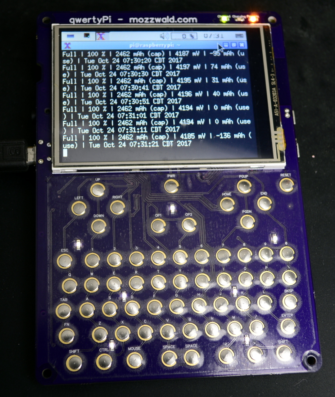
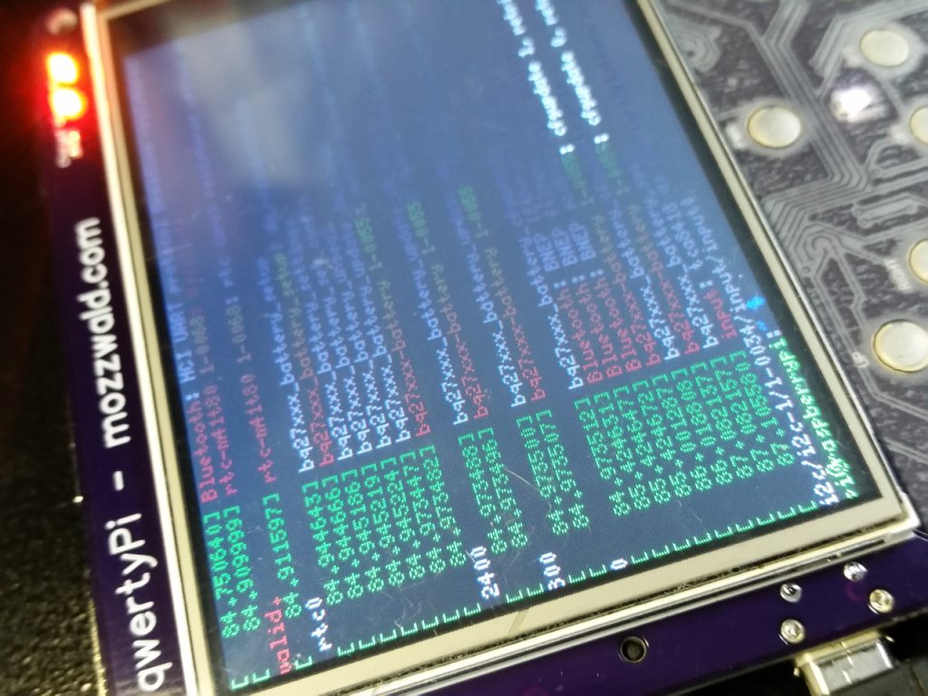
I wanted to have a true reading of battery life remaining so I went with a I2C battery fuel gauge IC, the TI BQ27621. I’ve experimented with this chip before but I recently found a pretty good linux driver for programming and reading the battery information which I ported to the raspi 4.13 kernel. The device tree overlay for the fuel gauge has 3 important settings that program the fuel gauge for the specific battery used: voltage-min-design-microvolt, energy-full-design-microwatt-hours, charge-full-design-microamp-hours.
LCD & Touchscreen
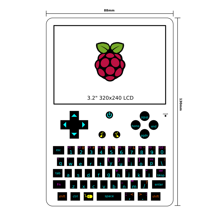
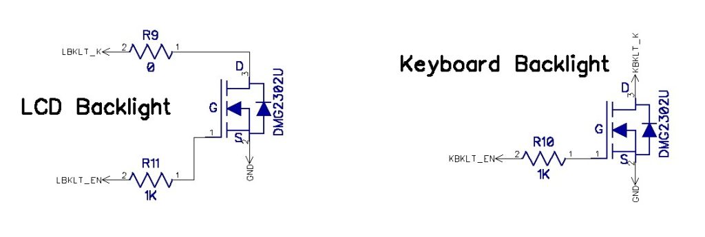
Searching Aliexpress for small LCD’s pulls in a ton of results. I then did some research into what SPI LCD’s were commonly used on the Raspberry Pi and settled on the ILI9341 chipset. I found this 3.2” 18 pin LCD with Touchscreen. I ended up making a small breakout board to test the LCD before incorporating it into the project. Originally, I was going to use a 3.3V LDO to turn on/off the backlight and my breakout has the circuit on it, but I ended up going with a MOSFET controlled by a GPIO. This allows me to use pi-blaster software PWM to dim the backlight. Pi-blaster works ok, but there is a backlight flicker when using anything lower than 100% and it’s more noticeable the lower you dim it.
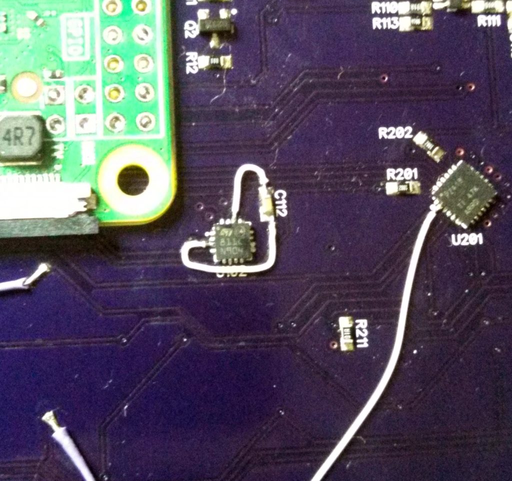
The touchscreen is controlled by a STMPE811. The chips came from the TGIMBOEJ I received way back when and I was thinking ahead for this project when I grabbed them from the box. I didn’t read the datasheet completely and missed the VIO pin on the chip which was left unconnected. This pin powers the touchscreen controller in the IC…oops. Adding a bodge wire got it working.
Keypad
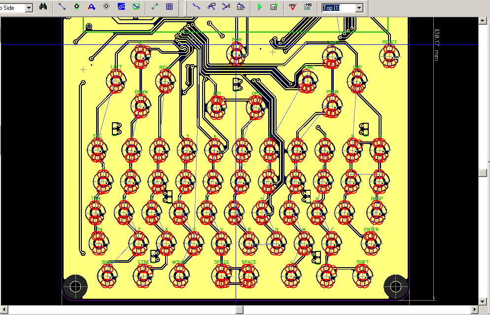
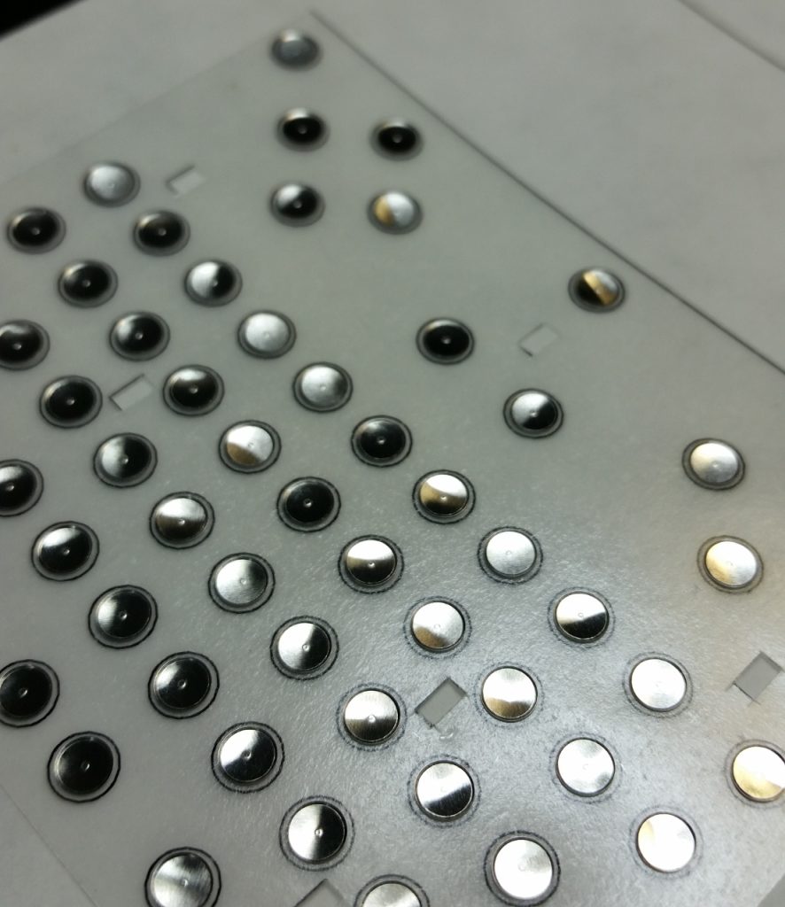
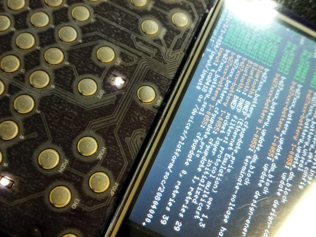
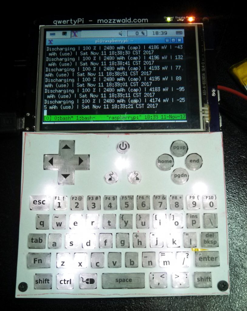
The main goal of the project is to have an almost full qwerty keypad with backlit keys. I’ve searched extensively for other examples of diy qwerty keypads which only brings up 3D printed pocket chip keyboards or raspi’s hacked together with mini USB/bluetooth keypads. Nothing where anyone actually makes their own circuit and keypad overlay from scratch. In the midst of working on this, I found moosepr on hackaday.io who made a tiny Pi Zero handheld gaming device and also started working on a qwerty handheld called the Pi0CKET Clicker. My design uses 4mm metal snap domes and a 3D printed keypad overlay. I needed to come up with a keyboard layout that would be comfortable and usable. With the help of some folks on twitter and irc I settled on a staggered ~60 key layout.
To make things easy for interfacing the keypad matrix I used the TI TCA8418 keypad IC. The chip has 8 rows and 10 columns and has a I2C Linux driver which makes it a perfect fit for my design. Setting up the Linux driver is as simple as compiling it and creating a device tree overlay with the proper keypad layout. I created a couple spreadsheets to aid in creating the keypad device tree overlay, one that converts the complete Linux keycode list from decimal to hex and another that contains the layout/matrix with hex keycode. A custom console keymap is loaded in /etc/rc.local with loadkeys during boot. I’m currently using a custom xinitrc for starting X which also loads a custom X keymap with xmodmap.
The keypad layout was drawn up in Inkscape. I used Inkscape a lot throughout the project to get everything lined up properly in Diptrace (my pcb cad program of choice). I created circles in Inkscape where each key should be (using my example layout as a guide) and imported that into the assembly layer of Diptrace. This allowed me to place each snap dome pad exactly where I wanted it. Diptrace has some qwerks and the pad I created for my keys is actually a shape with a pad inside the copper shape. This confuses Diptrace when running the Design Rule Check and throws errors for each key. It also shows many unconnected ratlines, even though they are technically connected with the copper shape. This caused me some issues when manually checking for errors in my first design and missed a few unconnected ratlines with the keypad. Also, I screwed up by adding some keys to the same row and column that shouldn’t be.
I really wanted a keyboard backlight for using this at night. The backlight circuit is the same as the LCD backlight with a MOSFET but with individual white LED’s and resistors. Pi-blaster is also used to dim the bright LED’s. Rev 1 only has 7 white LED’s which isn’t enough to cover the entire keypad. The rev 2 pcb will have 20 LED’s, but I may or may not use all of them. The flicker seen on the LCD isn’t really noticeable on the keypad backlight.
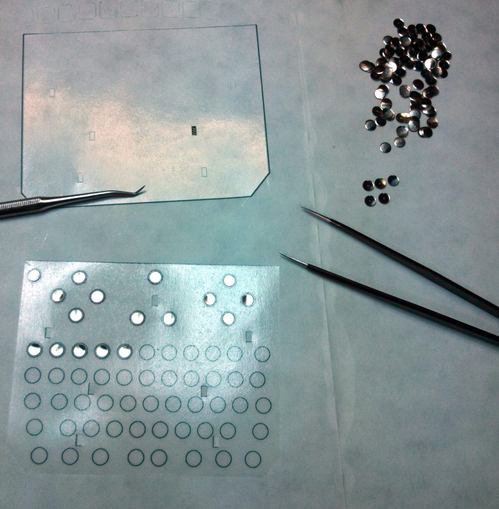
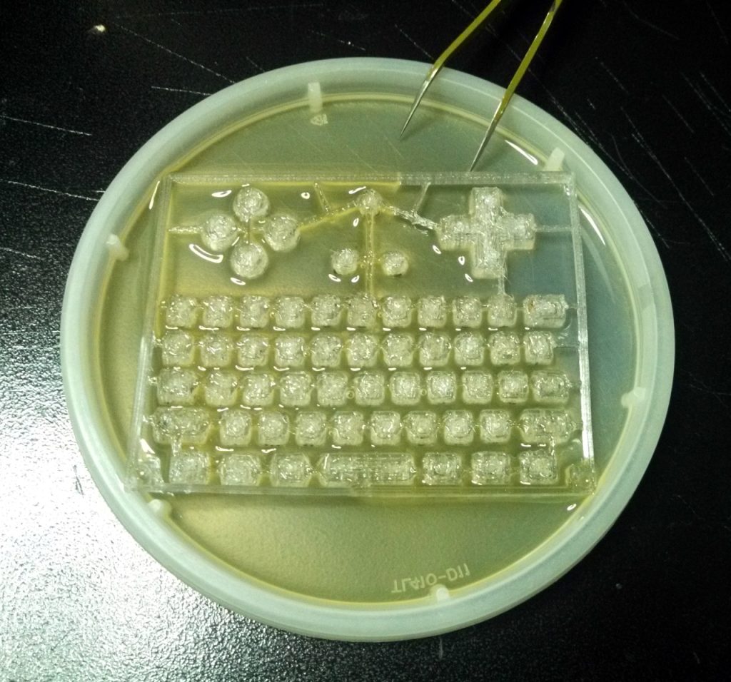
The snap domes are attached to the pcb with a clear sticky label. I printed the snap dome assembly layer onto a sheet of clear label with my laser printer and cut it out by hand with a razor blade, including the LED holes. The label was removed from the backing and each snap dome hand placed into it’s circle on the sticky side. Then, I carefully placed the label onto the pcb.
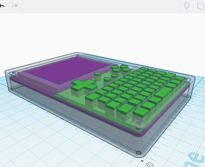
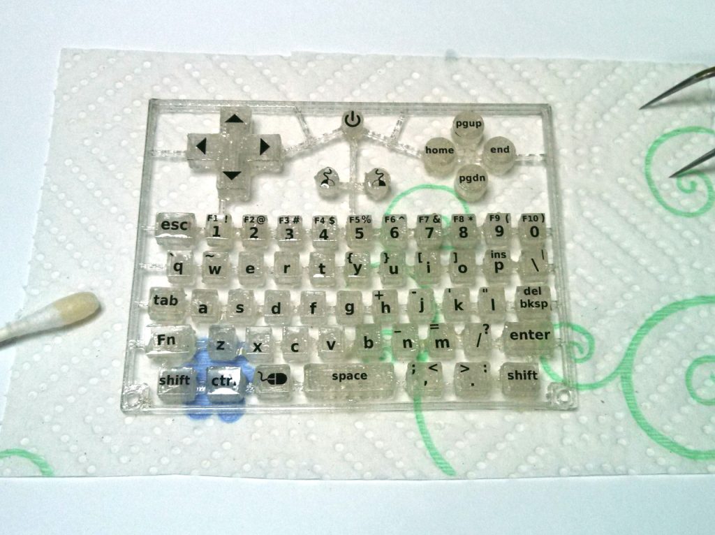
The button overlay I’m using now is 3D printed in clear/translucent TPU filament (like ninjaflex). My first design was quickly made as I found it quite difficult to use the snap domes alone and needed something to experiment with right away. 3D design is new to me considering I’ve only ever designed the Zipit Z2 expanded bottom case so I expected some issues. I really had no idea how flexible the TPU filament would be. Turns out, it’s really flexible. My first design had very thin connections between the buttons and the whole thing is really flimsy. The dimples that press the snap domes down didn’t turn out so well due to the support material that was added because of the way I designed the keypad frame. I ended up using a soldering iron to melt and move some of the support material to make better formed dimples on the keys that didn’t work well. My idea for the next iteration is to make a single thin layer of TPU with the buttons protruding upward and have a hole in the bottom center of each button. The dimples will be printed separately and glued into the holes.
A keypad isn’t usefull unless you know what they are so I printed some button labels, cut them out by hand and placed them on each button. The labels stuck well enough, but I decided to add a dab of clear Gorilla Glue before placing them. After the glue dried overnight, I dipped the buttons in polyurethane to protect them (two coats). So far, they’re holding up okay with light use. Since the keys moved around so much due to the flexible filament I cut holes for the keys on a piece of cardstock to keep them steady.
USB
I had high hopes of two USB Host ports using the Microchip USB2422 IC and being able to switch between the hub or Micro USB port for device mode. TI makes the TS3USB30 USB switch IC that allows switching a single set of USB data lines to two different endpoints. The switch seemed to work fine as I was able to use the Micro USB port for device mode, but I couldn’t get the hub to work at all. I should’ve read up more on how to route high speed USB traces. My traces went back and forth between the two layers too much and were not routed over the ground plane the whole way. After much troubleshooting I’ve decided to scrap the hub and USB switch. Instead, the next design will just have a single USB host port.
Sound
I decided to copy the headphone jack audio circuit from the Raspberry Pi B+ but I also wanted to use a single mono loud speaker. The TRS jack I picked out has an extra switch pin that connects to the Left audio out in the jack when the headphones are not plugged in. This output is sent to the speaker positive pin, but when headphones are connected the audio only goes to the jack.
The audio coming from the raspi pwm pins is good enough quality for me, but I noticed some noise on the output when there was some cpu activity. For example, if I was playing audio and connected via ssh, whenever I pressed a key (via ssh) there would be an audible tick in the sound output. The audio circuit is being powered from the raspi 3.3V supply and likely picked up interference from it. I whipped up a breakout board with a 3.3V LDO and attached it to the audio circuit and the audible noise disappeared. The schematic linked above shows the audio circuit being powered from AUD_2.5V which is likely another regulator on the Pi B+.
The loud speaker is not very loud so I picked up an Adafruit PAM8302 Mono amp and tested it out with the speaker which worked great. The rev 2 board has both the 3.3V LDO and Amp added on board.
Real Time Clock
Since the raspi has no real time clock and wifi may not always be available I added the tiny ST M41T62 RTC IC. This low power RTC has an integrated 32KHz crystal oscillator. The RTC is powered directly from the battery and is connected to the raspi over I2C. A Linux driver and device tree overlay is available which makes it a pretty easy chip to incorporate.