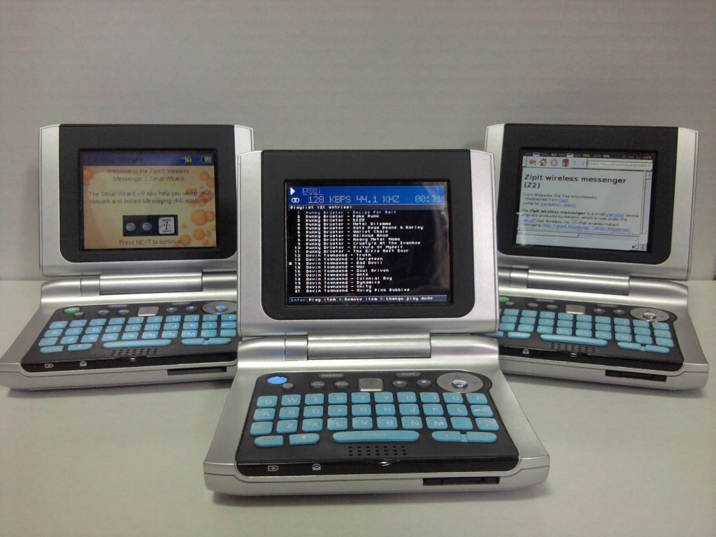
What is a Zipit Z2?
The Zipit Z2 Wireless Messenger was released in 2007 to be used by kids as a wifi enabled chat device. The Z2 originally came with it’s own application running on top of a Linux kernel. Soon after the device was released many people began to hack the device and get a new kernel and operating system to work on it. This page is intended to be an accumulation of information about hacking the device.
General Hardware Specifications
- Marvell PXA270 CPU @ 312mhz (overclockable)
- Marvell 802.11b/g Wifi (libertas driver)
- 32mb SDRAM
- 8mb NOR Flash Storage
- MiniSD memory card slot
- 2.8 inch QVGA color display
- 5V 2A DC Adapter Input
- Backlight QWERTY Keypad
- Headphone Jack
- Microphone and Remote control Jack (similar to Nintendo DS)
- 36 Pin Expansion (Hirose) Connector on back (see below for pinout)
- 3.7V 1230mAh Lithium Ion Battery Model ZWM2-1230LI (67mm x 60mm x 4mm)
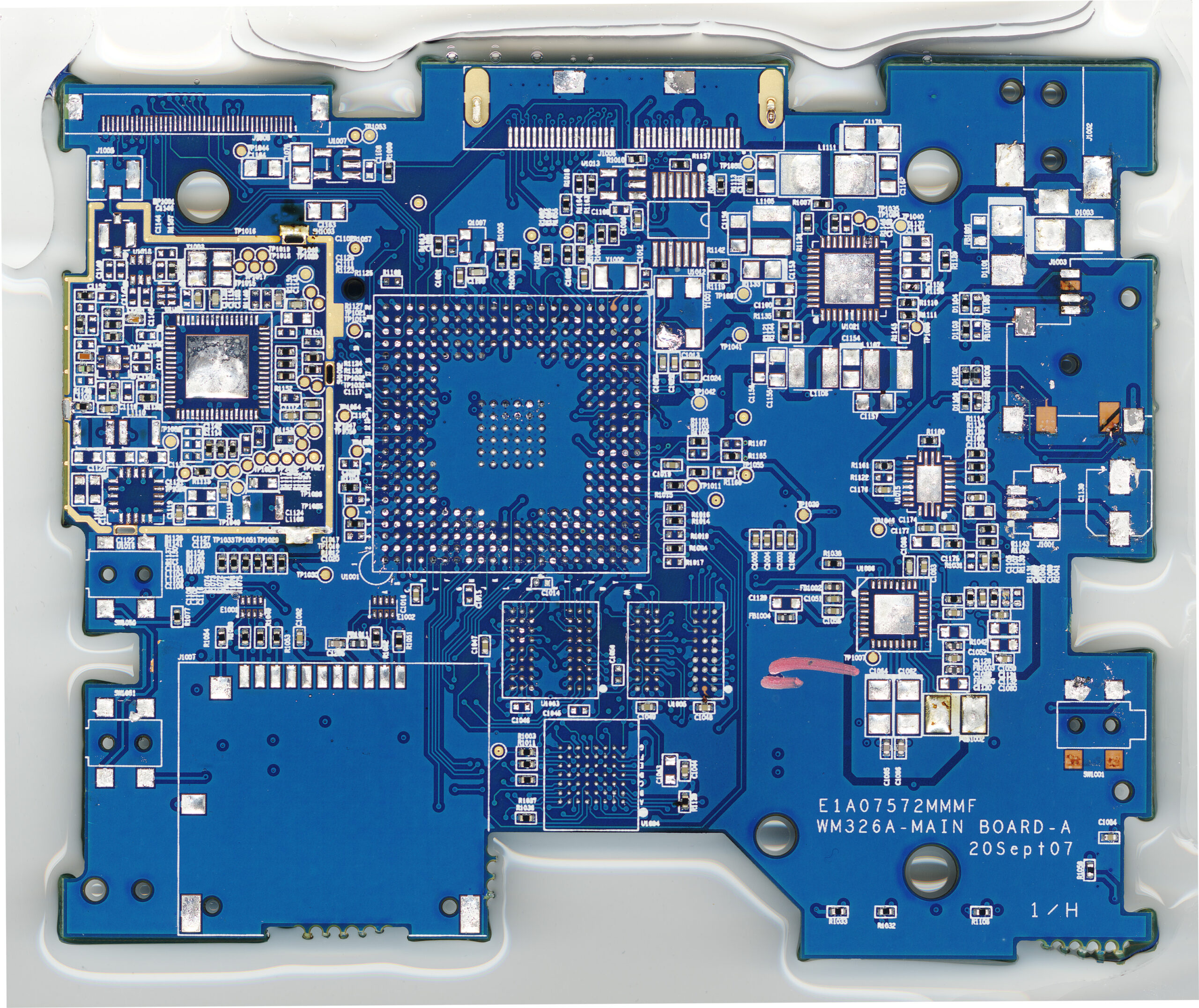
IC / Parts List
Here is the list of chips seen on the Zipit2’s board. This list contains all the major chips, their complete markings, and available information. (source)
- NHPXA270C5 G7064572.1 0728 C312 – Marvell PXA270 cpu @ 312mhz
- 88W8686-NAP1 KKN1605.3 0703 B2P ES TW – Marvell 802.11b/g Wifi Chip
- MRVL W886 738P – assumed to be a Marvell chip that works with the 88W8686
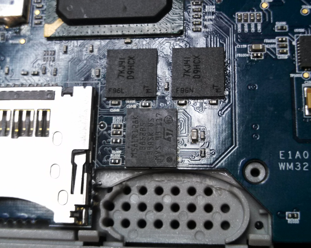
- 7KJ41 D9HCX – two Micron MT48H8M16LFB4-8 IT 16MB SDRAM chips
- 640W18BD 5720B148 Z202125D – Intel 28F640W18 8 MB Flash (Datasheet)
- WM8750BG 76AP6HF – Wolfson Audio Chip
- ANA TI 68k A3RF – Texas Instruments BQ24035 Charging & Power Path IC (Datasheet)
- TPS 65021 TI77k – Texas Instruments Power Management IC (Datasheet)
- AER915 5650001 YuG07 32A – Suspected to be the Aeronix version of the P89LPC915
- LP53 – Texas Instruments Ultra-Low Dropout Regulator (Datasheet)
- LMS283GF05 – Samsung 320×240 LCD (Datasheet)
- 20374-R40E-31 – IPEX LCD Connector (Datasheet)
- PJ1-022-SMT-TR – DC Power Jack (Datasheet)
- Maxim DS28CM00 – Device ID ROM (I2C ID 0x50)
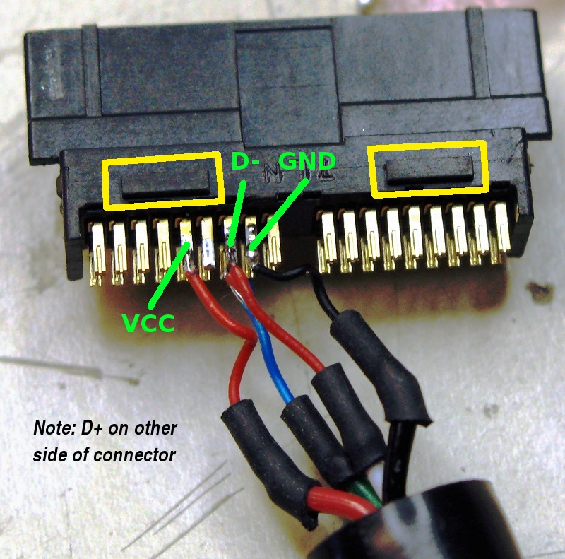
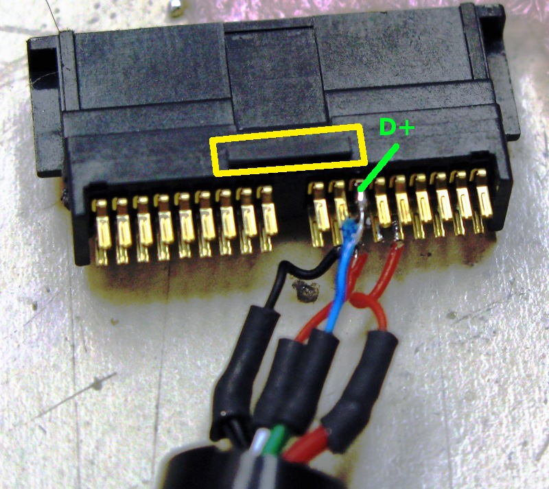
Expansion Connector
- Expansion connector plug (solder type for cable with housing): Hirose ST40X-36S-CV(80) (Old Part #) | Hirose ST40X-36S-CV(30) (New Part #)
- Expansion connector plug (SMT type for PCB): Hirose ST60X-36S (Old Part #) | Hirose ST60X-36S(30) (New Part #)
- Expansion connector Pinout (thanks jpb147)
Hardware Modifications
- 3.3V TTL Serial Mod
- Soft Keypad Mod
- ZipitBot
- Remote Control Pinout
- MicroSD Slot
- 16MB NOR Flash Upgrade (confirmed working)
- M58LR128KB85ZB5E (confirmed, obsolete)
- M58LR128KB85ZB6F
- M58LR128KB70ZB5E

- Z2 Breakout v1 | OSH Park Project
- Z2 Breakout v2 (mini) | OSH Park Project
- Nokia BP-4L Battery Replacement
- Possible 64 or 128MB RAM Upgrade:

Linux Distributions
- Easy Flash Script / Instructions
- OpenWRT
- openwrt-zipit (original/older) – github source | slug’s gmenu2x/jffs
- bleeding edge (openwrt-trunk, linux 4.4) – github source | bleeding edge repo | wiki
- IZ2JFFS – IZ2S that runs from stock internal flash
- Arch Linux
- Void Linux – Originally for Sharp Zaurus (OESF Forum, voidz github, voidz packages github)
- IZ2S (Buildroot based for Stock Zipit Z2)
- EZ2S (Based on IZ2S)
- z2sid (Debian Sid)
- z2lite (Buildroot)
- z2 Recovery OS (runs from internal memory)
- z2buntu (Ubuntu Jaunty)
- Rootnexus (Debian Sid/Lenny) (Wayback Machine)
- Sidetrack (Rootnexus Remix for Security/Penetration Testing)
- WejpOS (Buildroot)
- PlugApps – (Based on Arch Linux)
Kernel
- 3.x Kernel
- 4.x Kernel
Links
- http://linux.zipitwireless.com – Official Zipit Wiki (Wayback Machine)
- https://github.com/openwrt-zipit – OpenWrt Fork for Zipit Z2
http://www.chainxor.org/openwrt-zipit/ – OpenWrt Zipit Info- http://www.engine12.com – Slug’s Blog (Openwrt Zipit)
- http://macrofig.blogspot.com – Deeice’s Blog (IZ2S stuffs, misc Zipit)
- http://bealecorner.org/best/measure/z2/ – jpb147’s Zipit Info (hi-res photos, pinouts, etc)
http://www.hostwork.com/users/matt/zipitz2 – Wicknix’s Zipit info (z2lite & z2sid)- http://sweetlilmre.blogspot.com/search/label/zipit2 – sweetlilmre’s Blog (JTAG)
- http://www.notanon.com/ – Geordy’s Blog (misc Zipit info, hardware mods)
- http://www.russelldavis.org/ – RKDavis’ Blog (misc Zipit info, IZ2S/EZ2S)
- http://rayhaque.blogspot.com/search/label/zipit – Ray Haque’s Blog (IZ2S info)
- http://marex-hnd.blogspot.com/ – Marex’s Blog (u-boot)
http://justinbox.aresgate.net/html/make_page.php?n=zipitbot – Nulluser’s Zipitbot- http://zipitfan.wordpress.com/ – Fanoush’s Blog (u-boot keyboard support)
- http://uhrheber.wordpress.com/tag/zipit/ – Uhrheber’s Circuit Hell Blog (Zipit Bluetooth adapter)
- http://www.hunterdavis.com/ – Hunter Davis’s Blog (zipit, etc)
- Archive http://mendel.ugr.es/~ama/tmp/zipit/ – NeonLicht’s Zipit Page
GPIO List
Originally from here, updated by me
| GPIO | Direction | Function | Name | Note |
| 0 | in | 0 | (A/C power detect, present = 1) verified | |
| 1 | in | 0 | (reads 0 while power button pressed) verified | |
| 2 | in | 0 | ||
| 3 | in | 1 | ||
| 4 | in | 1 | ||
| 5 | in | 0 | ||
| 6 | in | 0 | ||
| 7 | in | 0 | ||
| 8 | in | 0 | ||
| 9 | out | 0 | ||
| 10 | out | 0 | (right-hand LED, on = 0) verified | |
| 11 | out | 2 | PWM_OUT<2> | LCD Backlight |
| 12 | in | 2 | CIF_DD<7> | Expansion Connector Pin 30 (PWM Capable) |
| 13 | out | 0 | ||
| 14 | out | 0 | Wifi Power Toggle | |
| 15 | out | 0 |
|
|
| 16 | in | 1 | KP_MKIN<5> | Keypad |
| 17 | in | 1 | KP_MKIN<6> | Keypad |
| 18 | out | 0 | ||
| 19 | out | 0 | LCD Reset | |
| 20 | out | 0 | ||
| 21 | out | 0 | ||
| 22 | out | 0 | ||
| 23 | out | 2 | SSPSCLK | verified |
| 24 | out | 0 | Wifi Chip Select | |
| 25 | out | 2 | SSPTXD | verified |
| 26 | in | 1 | SSPRXD | verified |
| 27 | out | 0 | ||
| 28 | out | 1 | I2S_BITCLK | |
| 29 | in | 1 | AC97_SDATA_IN_0 | (probably a bug, configured as I2S_SDATA_IN by blob) looks like the z2app uses it as an ac97 codec |
| 30 | out | 1 | I2S_SDATA_OUT | |
| 31 | out | 1 | I2S_SYNC | |
| 32 | out | 2 | MMCLK | |
| 33 | out | 0 | ||
| 34 | in | 2 | KP_MKIN<3> | Keypad |
| 35 | out | 2 | KP_MKOUT<6> | Keypad |
| 36 | in | 0 | IRQ | Wifi IRQ |
| 37 | out | 0 | (headphone detect, present = 0) | |
| 38 | in | 2 | KP_MKIN<4> | Keypad |
| 39 | out | 0 | ||
| 40 | in | 0 | ||
| 41 | out | 1 | KP_MKOUT<7> | Keypad |
| 42 | in | 1 | BTRXD | Expansion Connector Pin 7 (Breakout Board Dock Detection) |
| 43 | out | 2 | BTTXD | |
| 44 | in | 3 | CIF_FV | Expansion Connector Pin 36 (breakout board relay control) |
| 45 | out | 0 | CIF_PCLK / SSPSYSCLK3 | Expansion Connector Pin 31 |
| 46 | in | 2 | STD_RXD | |
| 47 | out | 1 | STD_TXD | |
| 48 | out | 0 | ||
| 49 | out | 0 | ||
| 50 | in | 1 | CIF_DD<3> | Expansion Connector Pin 26 |
| 51 | in | 1 | CIF_DD<2> | Expansion Connector Pin 25 |
| 52 | in | 1 | CIF_DD<4> | Expansion Connector Pin 27 |
| 53 | out | 2 | CIF_MCLK | Expansion Connector Pin 21 |
| 54 | in | 3 | CIF_PCLK | Expansion Connector Pin 20 (breakout board 5V Regulator enable) |
| 55 | in | 0 | (app reads) | |
| 56 | in | 0 | (app reads) | |
| 57 | in | 0 | (app reads) | |
| 58 | out | 0 | LDD<0> | LCD |
| 59 | out | 0 | LDD<1> | LCD |
| 60 | out | 0 | LDD<2> | LCD |
| 61 | out | 0 | LDD<3> | LCD |
| 62 | out | 0 | LDD<4> | LCD |
| 63 | out | 0 | LDD<5> | LCD |
| 64 | out | 2 | LDD<6> | LCD |
| 65 | out | 2 | LDD<7> | LCD |
| 66 | out | 2 | LDD<8> | LCD |
| 67 | out | 2 | LDD<9> | LCD |
| 68 | out | 2 | LDD<10> | LCD |
| 69 | out | 2 | LDD<11> | LCD |
| 70 | out | 2 | LDD<12> | LCD |
| 71 | out | 2 | LDD<13> | LCD |
| 72 | out | 2 | LDD<14> | LCD |
| 73 | out | 2 | LDD<15> | LCD |
| 74 | out | 2 | L_FCLK_RD | LCD |
| 75 | out | 2 | L_LCLK_A0 | LCD |
| 76 | out | 2 | L_PCLK_WR | LCD |
| 77 | out | 2 | L_BIAS | LCD |
| 78 | out | 0 | ||
| 79 | out | 0 | ||
| 80 | out | 0 | ||
| 81 | in | 2 | CIF_DD<0> | Expansion Connector Pin 23 |
| 82 | in | 0 | (app reads) | |
| 83 | out | 0 | Charging Amber LED 0 = enable (confirmed) | |
| 84 | in | 3 | CIF_FV | Expansion Connector Pin 35 (breakout board relay control) |
| 85 | out | 0 | (battery charge enable? 1 = inhibit, 0 = enable (according to battery LED)) | |
| 86 | out | 0 | Expansion Connector Pin 32 (breakout board relay control) | |
| 87 | out | 0 | ||
| 88 | out | 0 | LCD Chip Select | |
| 89 | out | 0 | ||
| 90 | out | 0 | ||
| 91 | out | 0 | ||
| 92 | in | 1 | MMDAT<0> | (bidirectional) |
| 93 | in | 2 | CIF_DD<6> | Expansion Connector Pin 29 |
| 94 | in | 2 | CIF_DD<5> | Expansion Connector Pin 28 |
| 95 | in | 0 | bq24035 Charging IC STATUS 2 Input, verified | |
| 96 | in | 0 | (MMC card detect – both edges active) | |
| 97 | out | 0 | ||
| 98 | in | 0 | clamshell / lid detect, open = 1, closed = 0 | |
| 99 | in | 0 | bq24035 Charging IC STATUS 1 Input, verified | |
| 100 | in | 1 | KP_MKIN<0> | Keypad |
| 101 | in | 1 | KP_MKIN<1> | Keypad |
| 102 | in | 1 | KP_MKIN<2> | Keypad |
| 103 | out | 2 | KP_MKOUT<0> | Keypad |
| 104 | out | 2 | KP_MKOUT<1> | Keypad |
| 105 | out | 2 | KP_MKOUT<2> | Keypad |
| 106 | out | 2 | KP_MKOUT<3> | Keypad |
| 107 | out | 2 | KP_MKOUT<4> | Keypad |
| 108 | out | 2 | KP_MKOUT<5> | Keypad |
| 109 | out | 1 | MMDAT<1> | |
| 110 | out | 1 | MMDAT<2>/MMCS<0> | |
| 111 | out | 1 | MMDAT<3>/MMCS<1> | |
| 112 | out | 1 | MMCMD | |
| 113 | out | 1 | I2S_SYSCLK | |
| 114 | in | 1 | CIF_DD<1> | Expansion Connector Pin 24 |
| 115 | out | 3 | PWM_OUT<1> | Keypad Backlight |
| 116 | out | 0 | ||
| 117 | in | 0 | (bit-bang I2C/SCL, mode 1 = low, 0 = high/input) | |
| 118 | in | 0 | (bit-bang I2C/SDA, mode 1 = low, 0 = high/input) | |
| 119 | in | 0 | ||
| 120 | in | 0 |