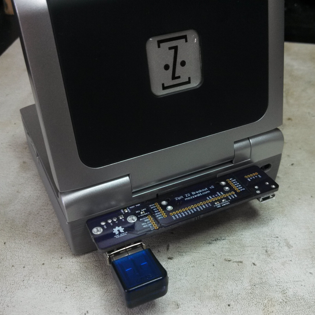
It’s been a year and a half since I came out with the first Z2 Breakout Board. They’ve all found new homes and hopefully some neat projects. I’ve considered making a new board since they all sold out but there isn’t really a Zipit market anymore. I think the buzz may have finally wore off although you can still find Zipits on eBay occasionally and hinv still has some for sale. Finally, I found the time to make a new board that is smaller and a better fit for the Zipit. The new board measures 75.11mm x 16.69mm which makes it sit much closer to the Zipit but extends further from side to side. There is a USB Host port (w/5V boost regulator), MicroUSB device port (charging input), 1.27mm breakout header for all 36 pins and special snap off sub-boards (if desired).
Update: I made a new v2.1 board which has a MOSFET that switches 3.3V ON or OFF via GPIO 51 to a through hole in the center of the board. The MOSFET is P Channel which means it is ON by default and writing a 1 to GPIO 51 will turn it off. This can be used for anything you like, but I added a tiny serial GPS module from SparkFun that fits perfectly over the USB Host port. Parts list and board are on the OSH Park Shared Project Page.
Update 2: I made yet another revision of the board that removes the snap off holes and adds two mounting holes. buZz from #zipit irc has made a nice little 3D printable docking station for the mini Zipit breakout board. I figured the holes would be a nice addition. Also, this board has room for an optional tantalum capacitor behind the USB Host port. Parts list and board are available on the OSH Park Shared Project Page. Gerbers can be found in the z2-breakout github repo
Both USB Ports are designed to be optionally broke off the middle ‘Main Zipit Board’. Score the board with a blade on both sides down the line of holes and snap off the end. Make sure the traces that pass in between the holes are cut enough so they do not get ripped up when the board is snapped off. Each board when broken off can be used independently as described later. The purpose of this feature is to allow for someone to easily implement their own docking station via the 36 pins. This idea came about after I posted my Expanded Zipit Bottom Case and it was suggested a ‘bump out’ section that surrounds the dock port be made.
Main Zipit Board
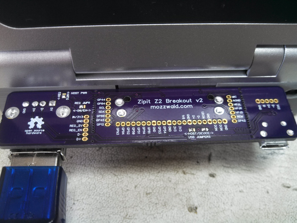
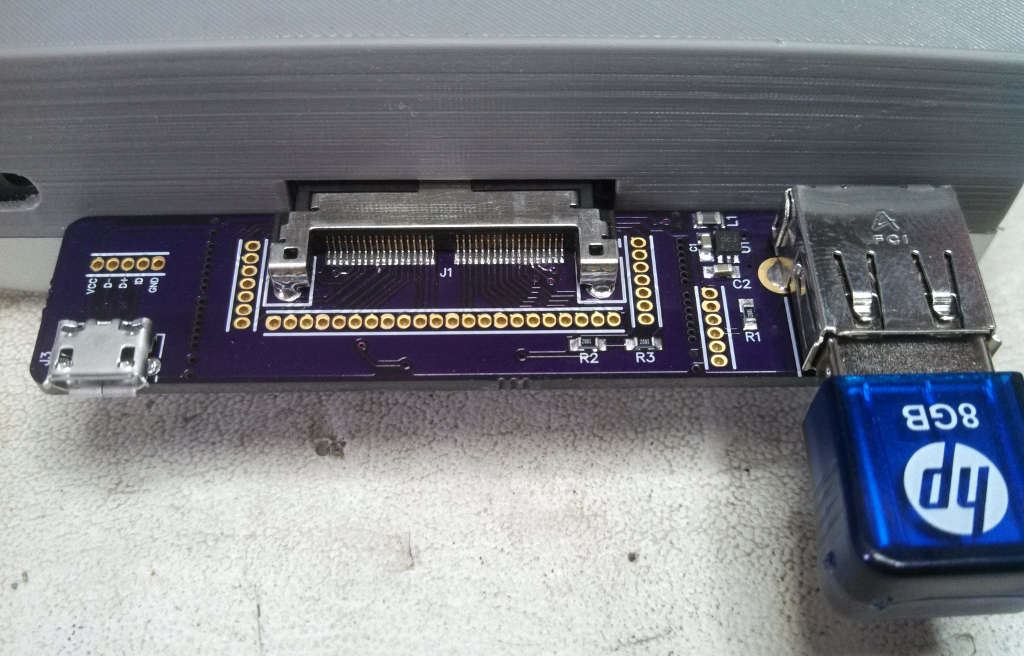
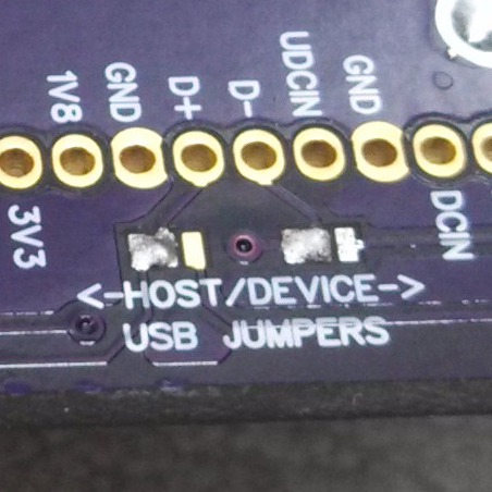
This section has the Hirose connector that plugs into the Zipit, 1.27mm pitch header pins, USB Host/Device solder jumpers and I2C pull up resistors. All 36 pins from the Zipit are broken out to 3 sets of 1.27mm through holes with silk screen labels on top. D+ and D- solder pad jumpers on the top can be used to route the USB data lines to the USB A Host port or the MicroUSB device port. Arrows point in the direction of the 2 pads to solder for Host or Device mode (left 2 pads for host, right 2 pads for device). Image on the left shows the board in Host Mode. Two 0603 resistors (R2, R3) are on the bottom and used to pull up SDA/SCL to 3.3V.
USB Host Board
Just like the v1 board, the new mini uses the same TPS61240 IC for 3.3V to 5V boost power. This (optionally) powers the USB Host port and is most useful when running the Zipit on battery. A solder jumper is provided to set Host port power from DC_IN or 5V Regulator. Another jumper sets the regulator to ON or EN. If set to ON, the regulator enable pin is connected to 3.3V which turns the regulator on whenever it is connected to the Zipit. EN requires GPIO54 to be high in order to turn on the regulator. This feature was added to aid in booting from a USB Device (Flash Drive) as described in my previous post.
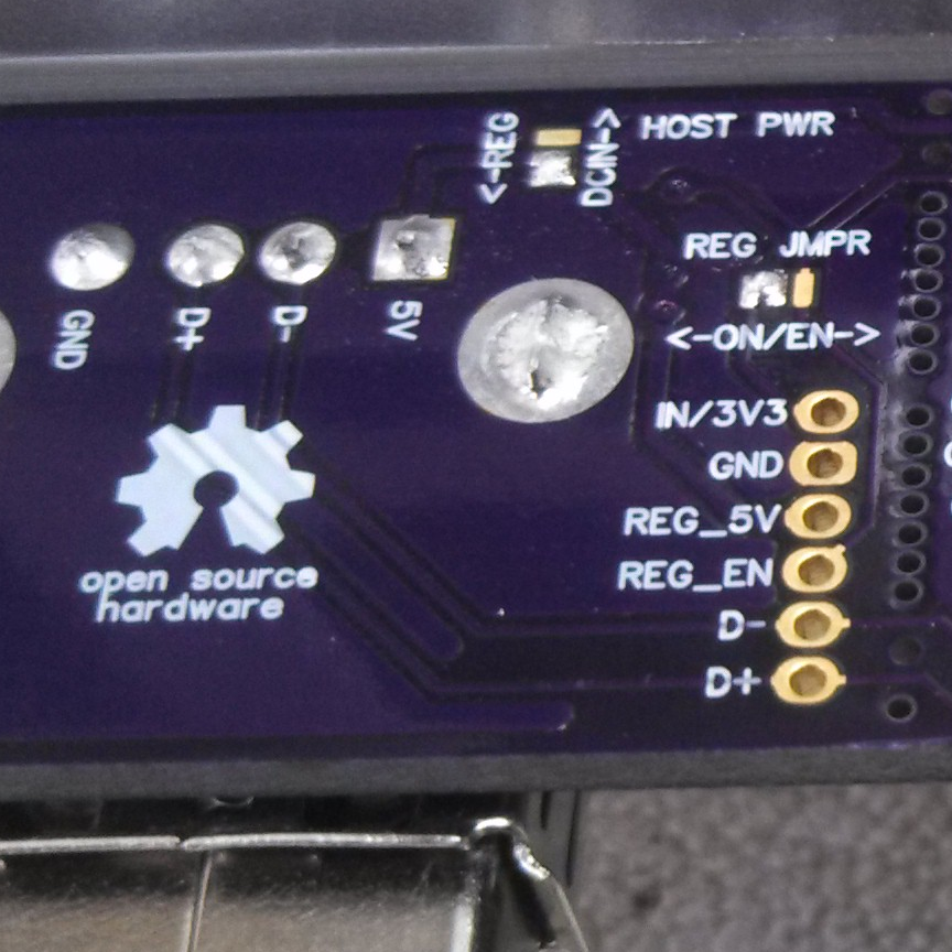
The USB Host board when separated from the Main Zipit Board can still be used. A 6 pin 1.27mm through hole header is provided for this and breaks out Input Power (IN/3V3), Ground (GND), Regulator 5V Output (REG_5V), Regulator Enable (REG_EN), D- and D+. The input power pin can accept (recommended range) 2.5V-5V. If the regulator solder jumper is set to EN, the REG_EN pin can be pulled high to turn on the regulator. If set to ON, IN/3V3 is tied to the enable pin and the regulator will be always on. Keep in mind, the maximum output current of the TPS61240 is 450mA.
MicroUSB Device Board
The MicroUSB Device board is quite simple. The VCC pin is connected directly to DC_IN (for charging the Zipit), GND to Ground, and D+ and D- to the USB data solder jumpers. When separated from the Main Zipit Board, the 5 pin 1.27mm through hole header allows it to be used as a typical MicroUSB Breakout. The ID pin is on the header but is not connected to the Zipit.
Parts List
PCB: Order from OSH Park
C1, C2: 4.7uF 6.3V 0603 (C1608X5R0J475K080AB)
L1: 1uH 0805 (LQM21PN1R0MC0D)
U1: TI 5V Regulator (TPS61240DRVT)
J1: Hirose to Zipit Connector (ST60X-36S(30))
J2: USB Host Port (292303-1)
J3: Amphenol FCI Micro USB Port (10118194-0001LF)
R1: 10K ohm 0603 Resistors (Regulator Enable)
R2, R3: 4.7k-10k ohm 0603 Resistors (I2C)
1.27mm Headers
Schematic & Board Layout
The board was designed using Diptrace 2.4. Schematics, board layout and gerbers are available in my z2-breakout github repo.
Final Thoughts
I still haven’t actually tested snapping off the sub boards, but it should work. I don’t have plans to make anymore and sell them. Most of the time I’m using a Zipit breakout board it’s for the USB port. This board is much better for that purpose. It’s slim profile and curved edges feel better when holding the Zipit.